
Introduction
Integrating a laser rangefinder into a stabilized UAV gimbal is not simply a matter of finding space for the module and connecting a power cable. The rangefinder needs to work as part of the complete payload while maintaining a stable relationship with the EO/IR imaging system, serving as a core ranging component responsible for accurate distance measurement within the entire payload system. For UAV payload designers and OEM engineers, several factors need to be considered during integration, including available installation space, module weight, mechanical mounting, optical alignment, power supply, communication interface, cable routing, and gimbal movement.
A well-designed integration process can help avoid problems that may only become apparent after the payload has been assembled or installed on the aircraft. This article explains the main considerations when integrating a 1535nm laser rangefinder module into a UAV gimbal, with a focus on practical mechanical, optical, electrical, and testing requirements.
Start with the Gimbal's Integration Constraints
Before finalizing the mechanical design, review the available space and interfaces inside the gimbal. The rangefinder should be evaluated as one component of the complete payload rather than as an independent device.
If the LRF has not yet been selected, see our guide on how to choose a 1535nm laser rangefinder module for UAV and EO/IR payloads.
Available Space
The first consideration is whether the module can physically fit within the gimbal.
Check:
- Module length, width, and height
- Mounting location
- Connector position
- Cable exit direction
- Clearance from surrounding components
- Gimbal rotation range
The available space can be particularly limited in compact EO/IR payloads, where the rangefinder may need to share the enclosure with visible cameras, thermal cameras, electronics, and other sensors. Many ERDI TECH laser rangefinder modules are designed with compact dimensions to simplify integration into space-constrained payloads. For OEM projects, the mechanical configuration can also be discussed according to the available installation space and system requirements. A compact module can provide more flexibility when arranging these components.
Weight and Center of Gravity
Weight is another important consideration for a stabilized gimbal.
The total mass of the payload affects the load on the gimbal motors, while the position of each component can influence the center of gravity.
For this reason, the LRF should not only be evaluated by its mass. Its installation position should also be considered during the mechanical design.
A lightweight rangefinder mounted close to the appropriate structural support can be easier to integrate than a heavier unit installed farther from the gimbal's center of rotation.
Mounting and Cable Routing
The mounting structure should provide sufficient rigidity to prevent unwanted movement during operation.
Cable routing should also be planned before the enclosure is finalized. The cable should not restrict gimbal movement, contact moving parts, or place excessive force on the connector.
For OEM projects, it is useful to review the rangefinder's mechanical drawing and connector definition before completing the final gimbal housing.
This can prevent avoidable mechanical changes later in the development process.
Mechanical Mounting and Optical Alignment
Mechanical installation and optical alignment are closely related in an EO/IR payload. A rangefinder may communicate correctly and produce valid distance measurements on a workbench, but its integration can still be problematic if its optical axis is not properly aligned with the imaging system.
Mechanical Mounting Rigidity
The LRF should be mounted firmly enough to maintain its position during:
- Gimbal movement
- UAV vibration
- Takeoff and landing
- Flight maneuvers
- Temperature changes
Small mechanical changes can affect the relationship between the LRF and the EO/IR camera.
For stabilized payloads, alignment should therefore be checked after the LRF has been installed in its final mechanical position rather than relying only on measurements made before installation.
Optical Axis and Boresight
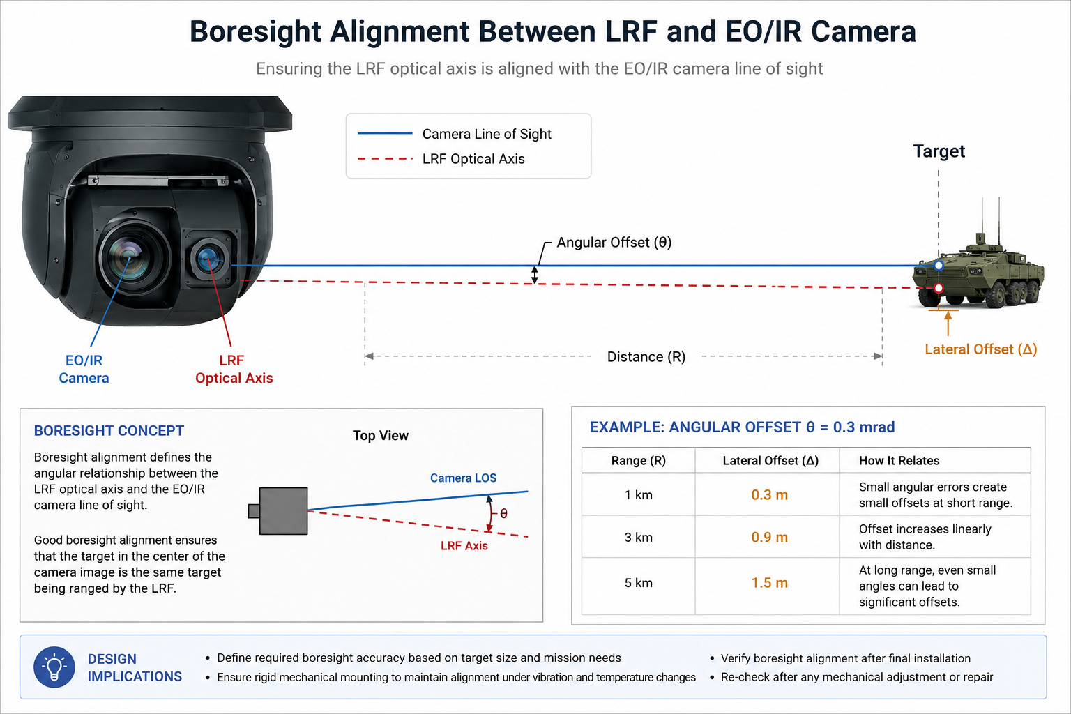
An EO/IR payload typically contains multiple optical channels. The camera has its own line of sight, while the laser rangefinder has its own optical axis. The system needs to account for the relative position and angle between them. This relationship is commonly referred to as boresight alignment.
If the rangefinder's optical axis is offset from the camera's line of sight, the target displayed near the center of the camera image may not be exactly the target being ranged. The effect becomes more significant as the distance increases. For example, an angular offset of 0.3 mrad corresponds approximately to:
- 0.3 m at 1 km
- 0.9 m at 3 km
- 1.5 m at 5 km
This does not mean that every system requires a specific 0.3 mrad alignment tolerance. The acceptable value depends on the payload's pointing accuracy, target size, operating range, and overall system design. The important point is that the required alignment should be considered during the mechanical and optical design stages.
Beam Divergence
Beam divergence is another specification that should be considered during integration. A smaller divergence angle generally allows the transmitted laser beam to remain more concentrated over distance. However, divergence should not be evaluated independently from the complete optical system.
The appropriate value depends on factors such as:
- Required measuring distance
- Target size
- Gimbal pointing accuracy
- Optical configuration
- Application requirements
Therefore, selecting a rangefinder should involve evaluating its optical characteristics together with the rest of the payload.
Electrical and Communication Integration
Once the mechanical configuration is established, the rangefinder needs to be connected to the UAV payload's electrical and control system.
Power Supply
Before installation, verify the electrical requirements of the selected module, including:
- Input voltage
- Operating current
- Average power consumption
- Peak or transient requirements
- Connector and pin definition
UAV payloads often operate under a limited power budget. The rangefinder should therefore be evaluated together with the power requirements of the camera, processor, gimbal controller, and other onboard electronics. A stable power supply is also important for reliable operation.
For OEM integration, the electrical interface should be confirmed before the final wiring harness and PCB design are completed.
Communication Interface
The rangefinder must exchange commands and measurement data with the payload controller. Depending on the model and system architecture, interfaces such as TTL or RS422 may be used. When integrating the module, engineers should confirm:
- Communication interface
- Baud rate
- Command format
- Measurement trigger
- Range data format
- Status information
- Error codes
- Connector definition
TTL can be suitable for certain internal connections, while RS422 can be useful when the system requires a more robust differential communication interface or longer cable connections. The important consideration is not simply which interface is available, but whether it is compatible with the payload controller and the intended wiring architecture.
Integration with the Payload Controller
In a typical UAV payload, the LRF does not operate completely independently. The measurement data may be transferred to a payload controller, onboard computer, EO/IR system, or ground station. A complete integration may therefore involve a data flow such as:
Laser Rangefinder → Payload Controller → EO/IR System → Ground Station
The exact architecture depends on the UAV platform and application. At the early stage of system integration, ERDI TECH can provide technical documentation such as communication interface specifications, pin definitions, parameter sheets, mechanical drawings, and 3D files. Having these materials available early can help OEM engineers evaluate mechanical and electrical compatibility before finalizing the payload design.
For OEM projects, having access to the communication protocol and relevant technical documentation before software development begins can significantly simplify integration.
Test the Integration Before Flight
A laser rangefinder should be tested as part of the complete payload before the first flight. Testing only the module on a laboratory bench does not verify whether it will perform correctly after mechanical installation and gimbal integration. A practical test sequence can include the following stages.
Bench Test
First verify basic operation:
- Power supply
- Communication
- Measurement commands
- Range output
- Basic target ranging
This confirms that the module and control system are communicating correctly.
Mechanical Installation Test
Install the rangefinder in its final position and check:
- Mounting stability
- Cable routing
- Connector clearance
- Gimbal movement
- Mechanical interference
The gimbal should be moved through its intended range of motion to ensure that the LRF and its cables do not interfere with other components.
Boresight Test
After final installation, verify the relative alignment between the LRF and the EO/IR imaging channel.
This step is particularly important if the payload uses the camera image to select the target to be ranged.
The alignment should be checked again after any major mechanical adjustment.
Static Ranging Test
Test representative targets at different distances.
Where possible, use targets with different sizes and reflectivity to understand how the integrated system behaves under realistic conditions.
The purpose is not simply to confirm the maximum range, but to verify that the system provides useful and repeatable measurements under the intended operating conditions.
Gimbal Movement Test
The rangefinder should also be tested while the gimbal changes its orientation.
Check whether:
- Range data remains stable
- Cables remain clear
- Mechanical alignment remains consistent
- The LRF remains synchronized with the imaging system
Ground Test
Once the basic integration has been verified, operate the complete payload on the UAV platform while the aircraft remains on the ground.
This provides an opportunity to evaluate the complete electrical, mechanical, and communication system before flight.
Flight Test
The final stage is flight testing under the intended operating conditions.
Flight testing should evaluate not only ranging distance, but also:
-
Ranging stability
-
Communication reliability
-
Gimbal performance
-
Target acquisition
-
Mechanical stability
-
Overall payload behavior
A staged testing process makes it easier to identify whether a problem originates from the rangefinder itself, the mechanical installation, the optical alignment, or the wider payload system.
What a Complete UAV LRF Integration Should Deliver
A successful integration should provide more than a functioning laser rangefinder.
The complete payload should achieve several results at the same time:
Stable Mechanical Installation
The module should remain securely mounted during gimbal movement and UAV operation without creating unnecessary mechanical or cable constraints.
Stable Optical Alignment
The relationship between the LRF optical axis and the EO/IR imaging channel should remain sufficiently stable for the intended operating distance and target accuracy.
Reliable Power and Communication
The rangefinder should receive a suitable power supply and communicate consistently with the payload controller.
Correct Range Data
The measured distance should be transferred to the appropriate onboard or ground system in a format that can be used by the complete payload.
Repeatable Performance
The integrated system should provide consistent operation during static testing, gimbal movement, ground testing, and flight.
These requirements are interconnected. A high-performance LRF cannot compensate for poor mechanical mounting, unstable power, incorrect boresight alignment, or an unsuitable communication architecture.
For this reason, integration should be considered from the beginning of the payload design rather than treated as the final step.
Conclusion
Integrating a 1535nm laser rangefinder module into a UAV gimbal requires coordination between mechanical design, optical alignment, electrical architecture, communication, and system testing. The most important considerations are not limited to the rangefinder's maximum measuring distance. Module dimensions, weight, mounting rigidity, optical axis, beam divergence, power requirements, communication interface, cable routing, and gimbal movement can all affect the final system. For UAV and EO/IR payload OEMs, reviewing these factors before the final payload design is completed can help reduce integration changes and make testing more efficient.
Need help with your UAV payload integration? Contact the ERDI TECH engineering team to discuss your requirements.
Email: yeva@erditechs.comWhatsApp: +86 18123396539